|
|
IEPE technology
IEPE: Integrated Electronics Piezo Electric
Trademarks of the sensor manufacturers: ICP, CCLD, Isotron, Piezotron etc.
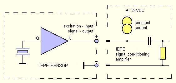
IEPE sensors for acceleration, vibration and noise, etc. are so-called "smart" transducers, i.e. besides
the actual piezo sensor element, they are additionally equipped with an impedance converter which permits
trouble-free handling
with respect to cable length and cable capacity, etc.
The IEPE sensor is powered by a constant current source, usually 4 mA from
24 V.
With this supply, a bias of typically +10 to +12 VDC is applied to the
IEPE sensor.
The sensor signal is an alternating voltage which is symmetrical
about this point.
Because of this DC bias, IEPE signal conditioner are always provided with an
AC coupling (high pass) at the input.
EIGNER MESSTECHNIK develops and manufactures a constantly expanding range of amplifiers and testing units
in the field of IEPE technology.
TEDS - Transducer Electronic Data Sheet (IEEE 1451)
Your question: Why don´t you offer the option of reading out TEDS data via
your modules?
Our answer: Because there has been no demand for it over the years.
|
IEPE Technik
IEPE: Integrated Electronics Piezo Electric
Handelsmarken der Sensor-Hersteller: ICP, CCLD, Isotron, Piezotron etc.
IEPE Sensoren für Beschleunigung, Vibration, Geräusch etc. sind sog. "smart transducer", d.h.
sie beinhalten neben dem eigentlichen Piezo-Sensorelement zusätzlich einen Impedanzwandler, was einen
unproblematischen Umgang bezüglich Leitungslänge, Kabelkapazität etc. ermöglicht.
Die Stromversorgung des IEPE Sensors erfolgt durch eine Konstantstrom-
quelle, meist 4mA aus 24V.
Mit dieser Versorgung stellt sich am IEPE-Sensor
ein Versatz von typisch +10 bis +12VDC ein.
Das Sensorsignal ist eine um diesen Punkt symmetrische Wechselspannung.
Aufgrund dieses DC-Versatzes werden IEPE-Signalaufbereiter am Eingang
immer mit einer AC-Kopplung (Hochpass) ausgestattet.
EIGNER MESSTECHNIK entwickelt und fertigt rund um die IEPE Technik eine stetig erweiterte Palette von
Verstärkern und Testgeräten.
TEDS - Transducer Electronic Data Sheet (IEEE 1451)
Ihre Frage: Warum bieten Sie keine Möglichkeit, TEDS Daten über Ihre
Module auszulesen?
Unsere Antwort: Weil es in den ganzen Jahren keine Nachfrage danach gab.
|
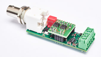
| IEPE signal conditioning modules
|
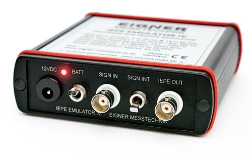
IEPE EMULATOR IV - IEPE test tool for sensor simulation
|
IPE-ISO1 - Precision Isolation Amplifier - with galvanic separation between:
INPUT / OUTPUT / POWER SUPPLY
|
Table: Function matrix of our current IEPE signal conditioning modules
|
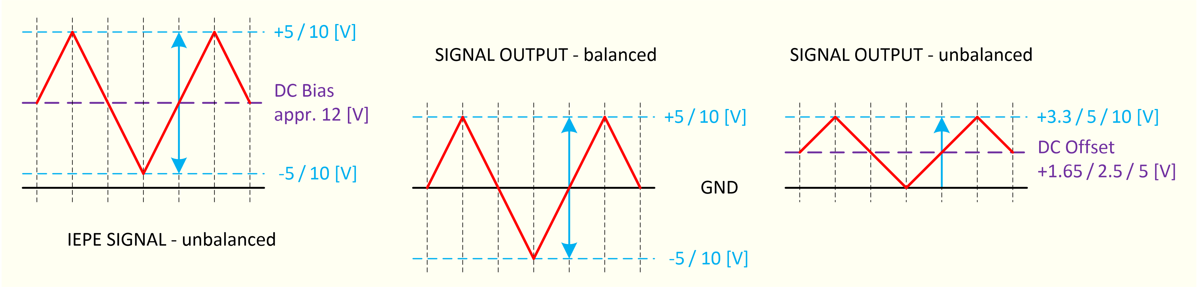
Diagram: IEPE signal compared to signal outputs of the modules
|
Select the module that best fits your measurement task:
One of the most important questions when selecting the appropriate IEPE signal conditioning is
whether the subsequent digitization unit (ADC) expects a
• symmetrical signal, ie ±5 V or ±10 V,
or whether the measuring range is
• unbalanced, e.g. 0 to +10 V, 0 to +5 V or 0 to +3.3 V.
Furthermore, it has to be clarified whether the sensor signal must be
• amplified, or even attenuated,
in order to enable a correct modulation of the subsequent digitization unit.
In addition, the IEPE excitation current must also be determined by means
of bandwidth and cable length.
• Range 2 to 20 mA. Default: 4 mA.
How important is an indication of the signal input status - OK or error?
Further question: Is for the measuring task an
• anti-aliasing filter
a) necessary or b) already installed at the digitization unit (ADC)?
If a: yes and b: no, then our module IPE-FM3, -FM6, -DM5 could be used.
Alternatively, we recommend our "Active Filters" modules.
In addition to the criteria listed in the matrix, particular attention should be
paid to the available power supply.
The modules IPE-FM4 and -FM6 have on-board charge pump
converters for generating both the
• negative operating voltage (-V_PS) of the electronics as well as the
• 24 V (nominal) IEPE excitation voltage (V_IEPE).
In addition to the usual 12 to 15 VDC, the IPE-FM6 module is also available
with a 24 VDC (22 to 26 VDC) power supply.
For the IPE-FM3 module, these voltages must be supplied externally.
These supply voltages are provided for the modules in the housings
(IEPE housing 1).
Wide range DC / DC converter
• 9 to 18 VDC or
• 18 to 36 VDC (optional 9 to 36 VDC)
allow galvanic separation of the supplies and a
automotive-compliant overvoltage protection.
IPE-FM4 and -FM6 also benefit from galvanic isolation, wide range
power supply and overvoltage protection.
IPE-DM5 is always supplied by DC / DC converters.
For details see data sheet "IPE-DM5_man_en.pdf".
|
Auswahl des zur Messaufgabe passenden Moduls:
Eine der wichtigsten Fragen bei der Auswahl der passenden IEPE-Signalaufbereitung ist,
ob die nachfolgende Digitalisierungseinheit (ADC) ein
• symmtrisches Signal, also ±5V oder ±10V erwartet,
oder ein
• unsymmetrisches, z.B. 0 bis +10V, 0 bis +5V oder 0 bis +3.3V.
Des weiteren muss geklärt werden ob das Sensor-Signal
• verstärkt, oder auch abgeschwächt
werden muss, um eine korrekte Aussteuerung der nachfolgenden Digitalisierungseinheit zu ermöglichen.
Ausserdem muss auch der IEPE-Erregerstrom an Hand von Bandbreite und Kabellänge festgelegt werden.
• Bereich 2 bis 20mA. Standard: 4mA.
Wie wichtig ist eine Anzeige des Signaleingangszustands - OK oder Fehler?
Weitere Frage: Ist für die Messaufgabe ein
• Anti-Aliasing-Filter
a) notwendig oder b) bereits vor der Digitalisierungseinheit (ADC) installiert?
Wenn a: ja und b: nein, bieten sich unsere Module IPE-FM3, -FM6, -DM5 an.
Alternativ empfehlen wir unsere "Aktive Filter" Module.
Neben den, in der Matrix aufgelisteten Kriterien, sollte besonderes Augen-
merk auf die zur Verfügung stehende Stromversorgung gelegt werden.
Die Module IPE-FM4 und -FM6 besitzen on-board Ladungspumpen-
Wandler zum Erzeugen sowohl der
• negativen Betriebsspannung (-V_PS) der Elektronik als auch der
• 24V (nominal) IEPE Erregerspannung (V_IEPE).
Neben den üblichen 12 bis 15 VDC ist das Modul IPE-FM6 auch mit einer
Spannungsversorgung von 24 VDC (22 bis 26 VDC) erhältlich.
Beim Modul IPE-FM3 müssen diese Spannungen extern zugeführt werden.
In den Gehäusen ( IEPE housing 1) werden diese Versorgungs-
spannungen für die Module bereitgestellt.
Weitbereichs DC/DC-Wandler
• 9 bis 18VDC oder
• 18 bis 36VDC (optional 9 bis 36VDC)
ermöglichen eine galvanische Trennung der Versorgungen und einen
automotive-gerechten Überspannungsschutz.
Auch IPE-FM4 und -FM6 profitieren von der galvanischen Trennung,
Weitbereichsversorgung und Überspannungsschutz.
IPE-DM5 wird grundsätzlich über DC/DC-Wandler versorgt.
Details siehe Datenblatt "IPE-DM5_man_de.pdf".
|
|
More information on request: info[at]eigner-messtechnik[dot]de Please specify in your enquiry mail the product you are interested in.
|
|
|