|
|
PRODUCTS
|
These product lines represent our
current spectrum of products in series production.
To receive our current price list please send an e-mail to: info[at]eigner-messtechnik[dot]de,
subject: "Request price list".
|
| | |
IEPE MODULES:
Very flexible
adaptation of an
IEPE SIGNAL
to the
SIGNAL OUTPUT
- balanced or
- unbalanced
Quick help with the
selection of our
IEPE devices:
IEPE device
selection
help form.pdf
|

Please note absolutely for all IEPE modules:
If the IEPE input is overdriven, or when the power supply is applied or switched on, the module output exceeds
(short-term) the nominal values up to the internal supply voltage of ±12 VDC.
Example for overloading: Instead of 0 to +5 V the output may take the values -1 to +6 V.
Therefore, make sure that your signal processing unit (ADC) can withstand these values without damage!
NEW from Dec 2024: IPE-FM6 as required with signal output limiting according to the selected output range of the module.
|
| | |
|
|
|
Important notes for ordering:
1. Please be sure to observe the different power (voltage) supplies of the various modules.
2. Please replace the placeholder letters
"V", "O", "F", "P" when requesting prices or
ordering modules with the desired values -
e.g. replace "V" with "A" or "B",
replace "O" with "4" or "8" etc.
|
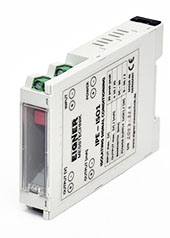
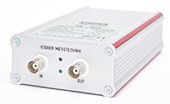
IPE-ISO1 / IPE-ISO1s
IEPE / AC / DC
3 ways
isolation amplifier
or
IPE-ISO1s
without galvanic
isolation
- balanced or
- unbalanced output
including
- Active Filters
and
- 4 to 20 mA output
as piggyback
module
Single supply:
9 to 36 VDC
→ IEPE modules
|
|
Versatile IEPE / AC / DC module adaptable to different signal inputs on different signal outputs with
IPE-ISO1: the galvanic isolation of signal input to signal output to power line,
IPE-ISO1s: without the galvanic isolation of signal input to signal output, but to power line.
Features:
- Wide input power supply 9 to 36 VDC, aprox. 2 W
- 3 DC/DC converters to the internal voltage supply of:
Signal input stage - IEPE excitation - Signal output stage
- Constant current excitation for IEPE Sensors 2 - 4 - 6 - 8 mA @ 28 VDC
- Input high-pass filter for decoupling the DC offset of the IEPE circuit
- Input stage with amplification or attenuation to adapt the IEPE level to the user prefered ADC
- Active filters: Pluggable low pass filter with Butterworth response 4th or 8th order
- Pluggable current loop signal output for the conversion of the voltage output 0 to 10 V to the
disturbance insensitive current output 4 to 20 mA (offset: 12 mA)
- Status LEDs - input signal within the normal range (green) or input signal outside the range (red)
- Avail. in 2 Versions:
A = DIN rail mounting or B = Aluminium housing
Order numbers - (Please quote this number when making price inquiries):
IPE-ISO1_V
IPE-ISO1s_V
Order numbers - Active Filters (Please name the desired cut-off Frequency):
IPE-FM6.3_BU_4_F: Butterworth low pass 4th order
IPE-FM6.3_BU_8_F: Butterworth low pass 8th order
Possible cut-off frequencies depending on the filter order -please watch the documentation.
Order numbers - Current Loop 4 to 20 mA (Please quote this number when making price inquiries):
IPE-ISO1-CIP
Product info: IPE-ISO1_info.pdf
[592 kByte info sheet in 'EN']
Broschüre: IPE-ISO1_man_de.pdf
[1735 kByte in 'DE']
Brochure: IPE-ISO1_man_en.pdf
[1731 kByte in 'EN']
|
IPE-FM1
|
|
No longer in our product range.
|
IPE-FM3
|
|
In the past, this module caused some confusion due to the multiple power supplies required for it:
+12, -12, +24VDC.
For this reason, it is no longer available as an individual module, but only integrated into the multi-
channel devices we manufacture according to your requirements. See → services
|
IPE-FM4
IEPE
signal conditioning
OEM module
- balanced or
- unbalanced output
Single supply:
12 to 15 VDC
→ IEPE modules
|


|
Upgrade to IPE-FM1 with the functional extensions:
- Input = Output range either ±10 V max. balanced to GND or
- Output = 0 to +10 V with offset +5 V for unbalanced AD-converters 0 to 10 V
- Output = 0 to +5 V with offset +2.5 V for unbalanced AD-converters 0 to 5 V
- Output = 0 to +3.3 V with offset +1.65 V for unbalanced AD-converters 0 to 3.3 V
- Input signal fault detection: open circuit or short to GND - indicated by ext. FAULT LED
Please specify when ordering: Fault LED A = fault (red)
or LED B = signal OK (green)
- Avail. in 2 Versions of installation:
A = suitable for front panel mounting or B = main board mounting
Order numbers - Balanced Output (Please quote this number when making price inquiries):
IPE-FM4.1-1_F_V: Input = Output (±10 V max.), DC Offset = 0 V
IPE-FM4.1-2_F_V: Input = ±10 V, Output = ±5 V, DC Offset = 0 V
IPE-FM4.1-3_F_V: Input = ±5 V, Output = ±10 V, DC Offset = 0 V
IPE-FM4.1-4_F_V: Input = ±2 V, Output = ±10 V, DC Offset = 0 V
IPE-FM4.1-5_F_V: Input = ±2 V, Output = ±5 V, DC Offset = 0 V
Order numbers - Unbalanced Output (Please quote this number when making price inquiries):
IPE-FM4.2-1_F_V: Input = ±10 V, Output = +10 V, DC Offset = +5 V
IPE-FM4.2-2_F_V: Input = ±5 V, Output = +10 V, DC Offset = +5 V
IPE-FM4.2-3_F_V: Input = ±10 V, Output = +5 V, DC Offset = +2.5 V
IPE-FM4.2-4_F_V: Input = ±5 V, Output = +5 V, DC Offset = +2.5 V
IPE-FM4.2-5_F_V: Input = ±10 V, Output = +3.3 V, DC Offset = +1.65 V
IPE-FM4.2-6_F_V: Input = ±5 V, Output = +3.3 V, DC Offset = +1.65 V
Product info: IPE-FM4_info.pdf
[382 kByte info sheet in 'EN']
Broschüre: IPE-FM4_man_de.pdf
[331 kByte in 'DE']
Brochure: IPE-FM4_man_en.pdf
[331 kByte in 'EN']
|
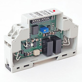
IPE-DM5
IEPE
signal conditioning
35 mm DIN RAIL
- balanced output
including
Active Filters
on board
Single supply:
9 to 18 VDC or
18 to 36 VDC
→ IEPE modules
|
NEW as of Oct 2022: →
IPE-DM5 also available in
a slightly simpler version
→ IPE-DM5s
|
The IEPE excitation and signal conditioning device IPE-DM5 is designed for installation in control
cabinets with 35 mm DIN rail mounting.
- Avail. in 2 Supply Power groups: 12 VDC (9 to 18) or 24 VDC (18 to 36)
Features:
- Constant current excitation for IEPE Sensors 4 mA @ 30 VDC
- Input high-pass filter for decoupling the DC offset of the IEPE circuit
- Amplifier with switchable amplification 1 - 2 - 5 - 10 [V/V]
- Active filters: 4th or 8th order Butterworth or Bessel low pass, 500 Hz to 20 kHz, Fcut-off as desired,
with one or two switchable frequencies, plus bypass switch
- Galvanic isolation of the measuring circuit from the 12 or 24 V control cabinet supply by means of
electrically isolated DC / DC converters for IEPE and device supply
Order numbers (Please quote this number when making price inquiries):
IPE-DM5.1_P: Signal conditioning without filters. New - Gain 1-2-4-8 (instead of 1-2-5-10)
IPE-DM5.2_P: Signal conditioning with one low-pass filter. New - Gain 1-2-4-8 (instead of 1-2-5-10)
IPE-DM5.3_P: Signal conditioning with two low-pass filters. New - Gain 1-2-4-8 (instead of 1-2-5-10)
IPE-DM5s.1.1/1.2_P: Signal conditioning without filters, Gain = 1 (1.1) or Gain = 2 (1.2)
IPE-DM5s.2.1/2.2_P: Signal conditioning with one low pass filter, Gain = 1 (2.1) or Gain = 2 (2.2)
IPE-DM5s.3.1/3.2_P: Signal conditioning with two low pass filters, Gain = 1 (3.1) or Gain = 2 (3.2)
Product info: IPE-DM5_info.pdf
[316 kByte info sheet in 'EN']
Broschüre: IPE-DM5_man_de.pdf
[1096 kByte in 'DE']
Brochure: IPE-DM5_man_en.pdf
[1095 kByte in 'EN']
Product info: IPE-DM5s_info.pdf
[310 kByte info sheet in 'EN']
|
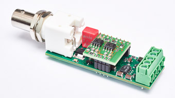
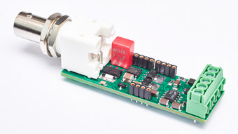
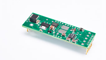
IPE-FM6
IEPE
signal conditioning
OEM module
- balanced or
- unbalanced output
including
Active Filters
as piggyback
module
Single supply:
12 to 15 VDC or
22 to 26 VDC
→ IEPE modules
NEW from Jan 2025:
As required with signal output limiting according to the selected output range of the module. Suffix: _SL
|
|
Versatile IEPE module adaptable to different signal inputs on different signal outputs.
Features:
NEW from Jan 2025:
- As required with signal output limiting according to the selected output range of the module.
- Single supply Power group: 12 VDC (12 to 15 VDC) or
24 VDC (22 to 26 VDC)
- Charge pump converter (100 kHz) for generating the internal supply voltages
- Constant current excitation for IEPE Sensors 4 mA @ 22 to 28 VDC
- Input high-pass filter for decoupling the DC offset of the IEPE circuit
- Input stage with amplification or attenuation to adapt the IEPE level to the user prefered ADC
- Active filters: Pluggable low pass filter with Butterworth or Bessel response 4th or 8th order
- Status LEDs - input signal within the normal range (green) or input signal outside the range (red)
- Avail. in 2 Versions of installation:
A = suitable for front panel mounting or B = main board mounting
- Avail. also with or without Signal Limitation:
N = without SL, Y = with SL
Order numbers - Balanced Output (Please quote this number when making price inquiries):
IPE-FM6.1-1_P_V: Input = Output = ±10 V, DC Offset = 0 V
IPE-FM6.1-2_P_V_SL: Input = ±10 V, Output = ±5 V, DC Offset = 0 V → _SL: ±5.5 V
IPE-FM6.1-3_P_V: Input = ±5 V, Output = ±10 V, DC Offset = 0 V
IPE-FM6.1-4_P_V: Input = ±2 V, Output = ±10 V, DC Offset = 0 V
IPE-FM6.1-5_P_V_SL: Input = ±2 V, Output = ±5 V, DC Offset = 0 V → _SL: ±5.5 V
IPE-FM6.1-6_P_V: Input = ±1 V, Output = ±10 V, DC Offset = 0 V
Order numbers - Unbalanced Output (Please quote this number when making price inquiries):
IPE-FM6.2-1_P_V_SL: Input = ±10 V, Output = +10 V, DC Offset = +5 V → _SL: -0.5 V
IPE-FM6.2-2_P_V_SL: Input = ±5 V, Output = +10 V, DC Offset = +5 V → _SL: -0.5 V
IPE-FM6.2-3_P_V_SL: Input = ±10 V, Output = +5 V, DC Offset = +2.5 V → _SL: -0.5 / +5.5 V
IPE-FM6.2-4_P_V_SL: Input = ±5 V, Output = +5 V, DC Offset = +2.5 V → _SL: -0.5 / +5.5 V
IPE-FM6.2-5_P_V_SL: Input = ±10 V, Output = +3.3 V, DC Offset = +1.65 V → _SL: -0.5 / +3.5 V
IPE-FM6.2-6_P_V_SL: Input = ±5 V, Output = +3.3 V, DC Offset = +1.65 V → _SL: -0.5 / +3.5 V
IPE-FM6.2-7_P_V_SL: Input = ±2 V, Output = +3.3 V, DC Offset = +1.65 V → _SL: -0.5 / +3.5 V
IPE-FM6.2-8_P_V_SL: Input = ±1 V, Output = +3.3 V, DC Offset = +1.65 V → _SL: -0.5 / +3.5 V
IPE-FM6.12-x_P_V: Input = by request, Output = by request, DC Offset = by request
Order numbers - Active Filters (Please name the desired cut-off Frequency):
IPE-FM6.3_BU_4_F: Butterworth low pass 4th order
IPE-FM6.3_BE_4_F: Bessel low pass 4th order
IPE-FM6.3_BU_8_F: Butterworth low pass 8th order
IPE-FM6.3_BE_8_F: Bessel low pass 8th order
Product info: IPE-FM6_info.pdf
[530 kByte info sheet in 'EN']
Broschüre: IPE-FM6_man_de.pdf
[645 kByte in 'DE']
Brochure: IPE-FM6_man_en.pdf
[643 kByte in 'EN']
|
| | |
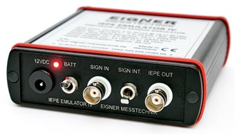
IEPE EMULATOR IV
IEPE sensor
simulation tool
→ IEPE EMULATOR IV
NEW from Oct 2024:
As an alternative to the
standard version -
IEPE EMULATOR IV "S"
|
|
IEPE EMULATOR IV facilitates the testing of amplifiers with IEPE inputs if there is no calibrated
engine test bench (shaker) for IEPE transducers available.
Special features: Battery powered, internal Sine Wave Generator 1024 Hz, bandwidth 0 to 50 kHz.
Output ±5 V, IEPE const. currents 2 to 20 mA at 18 to 30 VDC.
Product info: IEPE-EMULATOR-IV_info.pdf
[434 kByte info sheet in 'EN']
Broschüre: IEPE-EMULATOR-IV_man_de.pdf
[859 kByte in 'DE']
Brochure: IEPE-EMULATOR-IV_man_en.pdf
[859 kByte in 'EN']
NEW from Oct 2024:
As an alternative to the standard version -
IEPE EMULATOR IV S - no internal sine wave generator, no internal battery supply.
External signal feed, external power supply only. But reduced in price for this.
|
| | |
Active Filters:
module LHB 4-8
→ Active Filters
|
|
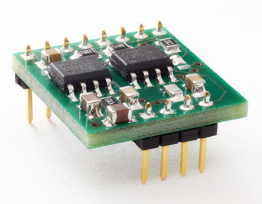
Active Filters LHB 4-8
LHB 4-8 is a pluggable module 18*16 mm², but connector grid 2.0 mm)
It is characterized by a large variability in the assembly:
- low pass or high pass, 2nd, 4th, 6th or 8th order
- high pass and low pass mixed as band pass filter (4th + 4th or 2nd + 6th order)
- filter characteristics: Butterwort, Bessel or Chebyshev - as band pass also mixed possible:
e.g. high pass with Bessel-, low pass with Butterworth-characteristic
- realizable frequency ranges high pass (X7R-equipped): from 0.1 Hz (freq. values always -3 dB)
- realizable frequency ranges low pass (COG-equipped): from 60 Hz (freq. values always -3 dB)
Product info: LHB_4-8_info.pdf
[398 kByte info in 'EN']
|
Active Filters:
module AF08
→ Active Filters
|
|
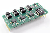
Active Filters AF08
AF08 is a pluggable module 22*48 mm², but connector grid 1/10 inch (2.54 mm)
AF08 ist available in 2 designs:
- A: single, fixed cut-off frequency filter
- B: switchable cut-off frequencies (also with remote control TTL/CMOS level) in 2-3-4 steps
with your preferred cut-off frequencies in the range of 50Hz to 50kHz.
You can order AF08 with filter responses "Butterworth" or "Bessel" with cut-off frequencies of your
choice.
Product info: AF08_info.pdf
[303 kByte info in 'EN']
Broschüre: AF08_man_de.pdf
[3926 kByte in 'DE']
Brochure: AF08_man_en.pdf
[3900 kByte in 'EN']
|
| | |
More information on request: info[at]eigner-messtechnik[dot]de Please specify in your enquiry mail the product you are interested in.
To receive our current price list please send an e-mail to: info[at]eigner-messtechnik[dot]de,
subject: "Request price list".
|
|