Test control unit for IEPE signal conditioning inputs
Transducers that operate in accordance with the IEPE principle have long
established themselves on the market as low-interference, easy-to-handle smart transducers for acceleration
and vibration, etc.
The test control unit IEPE EMULATOR IV is designed to test signal processing amplifiers for IEPE sensors.
It replaces real IEPE sensors for the cases
where no calibrated shaker is available for generation of exact
and reproducible test signals.
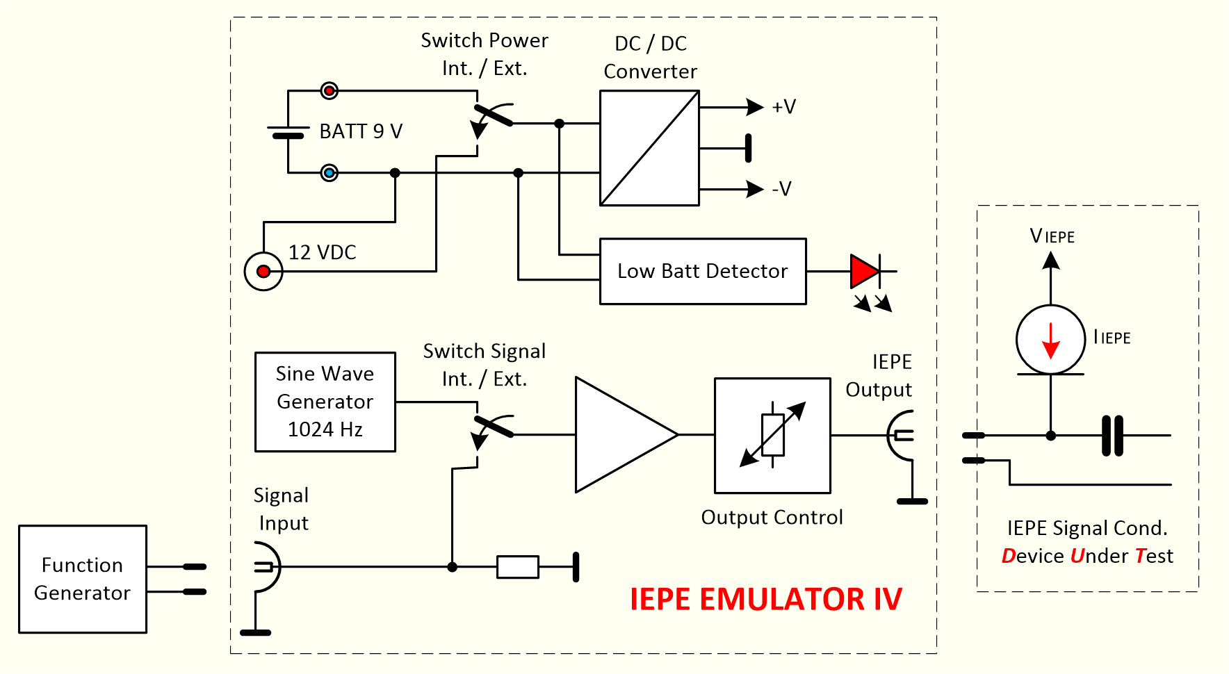
Principle of operation:
In view of the fact that, dependent on the type, IEPE sensors are operated with a load-independent current of
between 2 and 20 mA from a DC supply point
of 24 V (18 to 30 VDC), it is not possible to just feed the test signals into
the inputs of IEPE amplifiers. The test signal virtually "works" against the IEPE current and the high IEPE voltage.
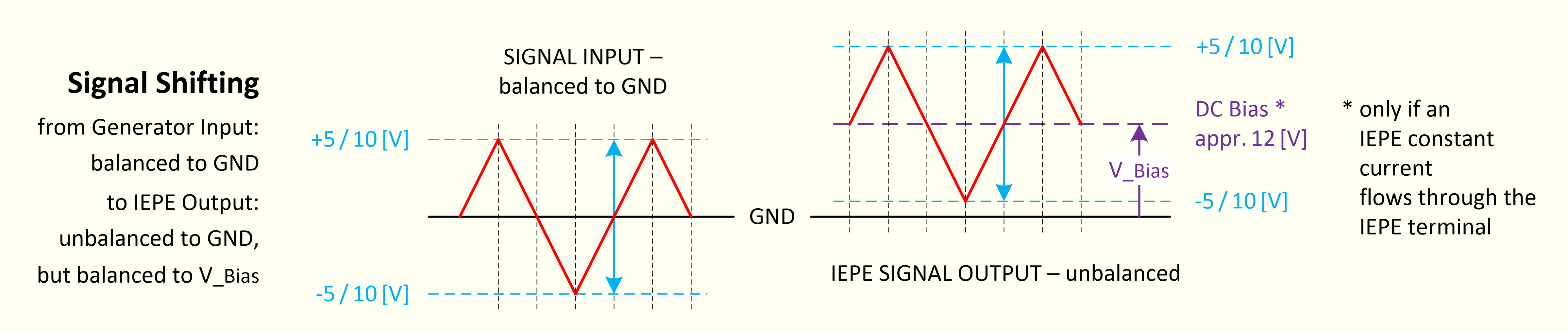
A circuit was therefore developed which emulates the quiescent potential.
The quiescent potential is about one-half of the IEPE supply voltage, thus approx. +10 to 12 VDC.
The test signal is coupled to the output stage and superimposes the test signal AC voltage on this quiescent DC voltage.
(See the block schematic).
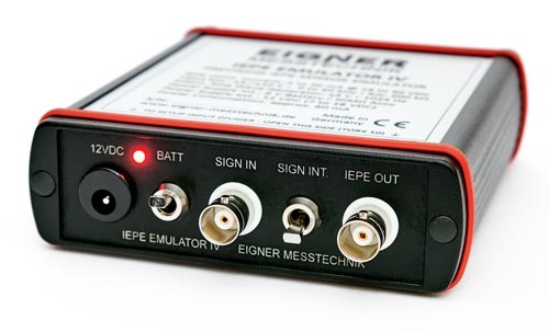
Connectors and switches on the front:
• DC connector for external power supply 12 VDC (7 to 18 VDC)
• BNC socket "SIGN IN" for external test signal 0 to ±5 VAC (±10 VAC)
• BNC socket "IEPE OUT" for connection of the test object
(Device Under Test - IEPE signal conditioning)
• Switch "BATT" for selection of power supply -
external 12 VDC or internal battery (or NiMH accumulator) 9 V)
• Switch "SIGN INT" for selection of test signals - external via BNC "SIGN IN"
or internal sine wave generator (1024 Hz / ±4 VAC)
Elements of the rear panel:
• Battery holder for 9V battery block
• Cover cap for water and dust protection
|
Prüfgerät für IEPE Signalaufbereitungseingänge
Messwertaufnehmer nach dem IEPE-Prinzip haben sich als störungsarme,
leicht zu handhabende Smart Transducer für Beschleunigung, Vibration etc. seit längerem am Markt etabliert.
Das Testgerät IEPE EMULATOR IV ist für die Prüfung von Signalaufberei-
tungsverstärkern für IEPE-Sensoren konzipiert.
Es ersetzt reale IEPE-Sensoren für die Fälle, in denen kein kalibrierter Prüfstand (Shaker) für die Generierung
von exakten, reproduzierbaren Testsignal zur Verfügung steht.
Funktionsprinzip:
Da IEPE-Sensoren je nach Typ mit einem eingeprägten Strom von 2 bis 20mA aus einer DC-Spannungsquelle von
ca. 24V (18 bis 30VDC) betrieben werden, ist eine direkte Einspeisung von Testsignalen in die Eingänge von IEPE-Verstärkern nicht
so ohne weiteres möglich. Das Testsignal "arbeitet" quasi gegen die IEPE-Stromquelle und die hohe IEPE-Versorgungsspannung.
Deshalb wurde eine Schaltung entwickelt die das Ruhepotential des IEPE-Sensors nachbildet.
Das Ruhepotential beträgt etwa die halbe IEPE-Versorgungsspannung, also ca. +10 bis 12V.
Das Testsignal wird an die Ausgangsstufe angekoppelt und überlagert diese Ruhe-Gleichspannung mit der
Testsignalwechselspannung. (Siehe Prinzip-Schaltbild.)
Anschlüsse und Schalter auf der Front:
• DC-Stecker für externe Stromversorgung 12VDC (7 bis 18VDC)
• BNC-Buchse "SIGN IN" für externes Testsignal 0 bis ±5VAC (±10VAC)
• BNC-Buchse "IEPE OUT" zum Anschluss des Testobjekts
(Device Under Test - IEPE Signalaufbereitung)
• Schalter "BATT" für Auswahl der Stromversorgung -
extern 12VDC oder interne Batterie (oder NiMH Akkumulator) 9V
• Schalter "SIGN INT" zur Wahl der Testsignale -
extern über BNC "SIGN IN" oder interner Sinusgenerator (1024Hz / ±4VAC)
Elemente auf der Rückseite:
• Batterieaufnahme für 9V Batterieblock
• Abdeckkappe für Wasser- und Staubschutz
|